3-Phase Transformer – Construction & Working Principle
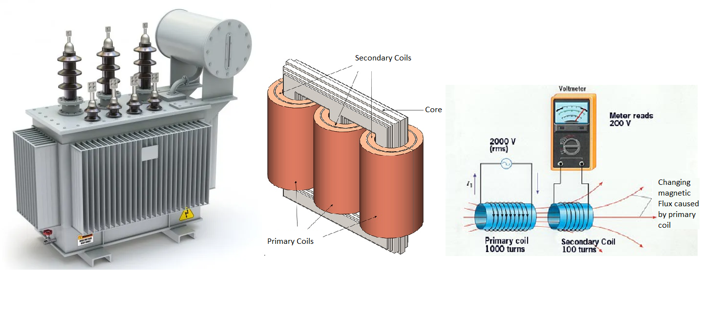
3-phase transformers transfer electrical energy between circuits without changing the frequency. They step up or step down voltages through magnetic induction in the secondary circuit. These transformers are compatible with three-phase AC electrical systems, ensuring stable and safe electricity for various industries and applications. The size, design, volt-ampere rating, and load-bearing capacity of a three-phase transformer vary depending on the specific requirements of the system it serves.
TYPES OF TRANSFORMERS
Conventional Transformers:
- Power Transformers
- Generator Transformers
- Dry type Transformers-VPI
- Dry type Transformers – Cast Resin
- Unitized substation Dry
- Mining Transformers
- Neutral Grounding Transformer
- Auto Transformers
- Auto Transformers starting
- Lighting Transformer
- Isolation & Ultra isolation Transformer
- Automatic Voltage controller
- Lighting & Furnace Transformers
- Earthing Transformers
- Control Transformer’s
- Dry type Auto Transformer
Sealed Transformers:
- C S P Transformers
- Corrugated Transformer
- Corrugated Transformer – without sealed
Converter / Furnace Transformers:
- Rectifier Transformer
- Furnace Transformers – Induction
- Furnace Transformers — Submerged Arc
- Traction Transformer
- Reactor Transformer Air cored
- Reactor Transformer Iron cored
- Phase conversion Transformer
- Converter transformer
Special Application Purpose:
- Bucking- Boosting Transformers
-
Sensing Transformer’s
Vidyut Cloud is a cutting edge B2B E-commerce marketplace for the electrical Products
STANDARD KVA RATING’S OF TRANSFORMER’S:
KVA KVA KVA KVA KVA
5 31.5 200 1250 7500
6.3 40 250 1500 8000
8 50 315 1600 10000
10 63 400 2000 12500
12.5 80 500 2500 13500
16 100 630 3150 15000
20 125 800 5000 16000
25 160 1000 6300 20000
STANDARD VOLTAGE RATIO’S OF TRANSFORMER’S:-
11000/433 V 33000/690 V
22000/433 V 22000/11000 V
33000/433 V 33000/11000 V
11000/690 V 132000/11000 V
22000/690 V 132000/33000 V
SPECIAL V.RATIO’S OF TRANSFORMER’S:-
1. DUAL RATIO 33 -22/0.433KV & 33 -11/0.433KV&22 – 11/0.433KV
2. CONVERTER DUTY
3. FURNACE DUTY 11000/575 V @0.95 P.F &33000/575 V @ 0.95P.F
4. FURNACE DUTY (6-12-18-24pulses) 33000/2X1000V & 11000/2X690V (1:2 OR 1:3)
5. RECTIFIER DUTY
6. INVERTER DUTY(6&12pulse) 11000/2X280 V – Dd0yn11
REFERANCE STANDARDS FOR TRANSFORMRS:
- IS 2026 – Indian Standard (Oil Type)
- IS 1180 – Indian Standard (Oil Type)
- IS 11171 – Indian Standard (Dry Type)
- IEC 60076 – International Electrotechnical Commission (Oil Type)
- IEC 60076 (Part-11) – International Electrotechnical Commission (Dry Type)
- ANSI – American National Standards Institute
- CBIP – Central Board of Irrigation and Power
- ECBC – Energy Conservation Building Code
- SANS – South African National Standard
- EU- ECO – European Eco Designs
- GOST – Group of Standards Developed in Soviet Union
- WAPDA – Water & Power Development Authority
TRANSFORMER COOLING TYPES:-
Cooling for oil immersed transformer:
1. ONAN : Oil Natural Air Natural
2. OFAN : Oil Forced Air Natural
3. OFAF : Oil Forced Air Forced
4. ANAN (VPI) : Air Natural Air Natural (Vacuum Pressure Impregnated)
5. ANAN (CRT) : Air Natural Air Natural (Cast Resin Transformer)
6. ANAF (VPI) : Air Natural Air Forced (Vacuum Pressure Impregnated)
7. ANAF (CRT) : Air Natural Air Forced (Cast Resin Transformer)
8. KNAN : Non-Mineral Oil Such as Silicone Oil, Synthetic Ester or Natural Ester
CURRENT DENSITY IN THE TRANSFORMER:
It is the current carrying capacity of a wire per unit cross sectional area. It is expressed
in units of Amp/ mm².
Maximum current density allowable for Aluminum oil type transformer-1.8,for dry type
transformer it will be 1.5
TRANSFORMER IMPEDANCE :
“The percentage impedance of a transformer is the volt drop on full load due to the winding
resistance and leakage reactance expressed as a percentage of the rated voltage.”
WOUND:
1. Copper single wound : For auto transformers
2. Copper Double Wound : For Power & Distribution Transformers
3. Multi Winding : For Rectifier or Converter or Induction furnace transformers with primary 11KV or 33 KV,
secondary 1(D) — V (— % of total KVA), secondary 2 (U) —- V (—- % of total KVA) may have more secondary’s
for various applications, percentage KVA of secondary depends on number of secondary’s. If 2 secondary’s than
50% of primary KVA, If 4 secondary’s than 25 % of primary KVA.
NUMBER OF PHASES:
1. Single phase : Primary single phase and Secondary single phase –
2 wire or 3 wire.
Three phase : Primary three phase and Secondary three phase.
2. Three phase to Single phase : Primary three phase and Secondary single phase.
FREQUENCY:
1. It is the frequency at which the transformer is designed to operate. In India the standard frequency for all the
power transformers is 50 Hz with targeted limits 50 ± 3 %, in USA the frequency is 60 Hz. The 50 Hz transformer
can be used for 60 Hz, but 60 Hz transformer can’t be used for 50 Hz.
Hertz (Hz) = Number of cycles per second.
TERMINAL ARRANGEMENT:
1. The conducting part to which the line conductor of external system is connected.
2. Types of terminal arrangements :
a. Bare bushings
b. Cable box
c. Bus duct Chamber
d. Disconnecting Chamber (D.C.)
e. Disconnection chamber is used only for
1. Government tenders and consultants.
2. Other than govt. deviation as disconnection of cable along with gland plate.
VOLTAGE VARIATION:
The transformer built in accordance with IS 2026 can be operated with ± 10 % of the primary rated
voltage at any tap.
FREQUENCY VARIATION:
Normal frequency variation is ± 3%
FAQs
1) What is the principle of Transformer ?
A transformer operates on the principle of mutual induction, where a change in magnetic flux linked with one coil induces an electromotive force (emf) in an adjacent coil.
2) What is the construction of Transformer ?
It comprises two insulated wire coils, the primary and secondary, wound on a laminated soft iron core. The coils are fully isolated from each other, with one usually having more wire turns. The frame is typically rectangular, and the coils can be wound on opposite bars or stacked on a central bar.
3) What is the Static Transformer ?
The static transformer utilizes electromagnetic induction to modify alternating current voltage and ensure current is free from grounding.
4) What is the working of Transformer ?
An alternating current is applied to the primary coil, creating a changing magnetic field that interacts with the secondary coil, inducing an electromotive force (EMF). It’s crucial for the intensity of the primary current to vary to facilitate the movement of the magnetic field relative to the conductor and induce EMF in the secondary coil. The primary and secondary coils are not electrically connected, and energy is transferred through electromagnetic induction. The core, typically made of soft iron, concentrates the magnetic field and is laminated to prevent eddy currents.
5) What are the functions of Transformer ?
- Alters the voltage of an alternating current: The EMF induced in the secondary coil depends upon the number of turns of wire it has, relative to the primary coil. Depending on this number of turns, the transformers can be classified as:
- Step-up transformer- If the number of turns in the secondary is more than that of the primary, the voltage developed in the secondary will be increased or stepped up. Such a device is called a step-up transformer.

One thought on “Perfect 3-Phase Transformer – Construction & Working Principle”